Wireless Network
Module 7 - Wireless Network
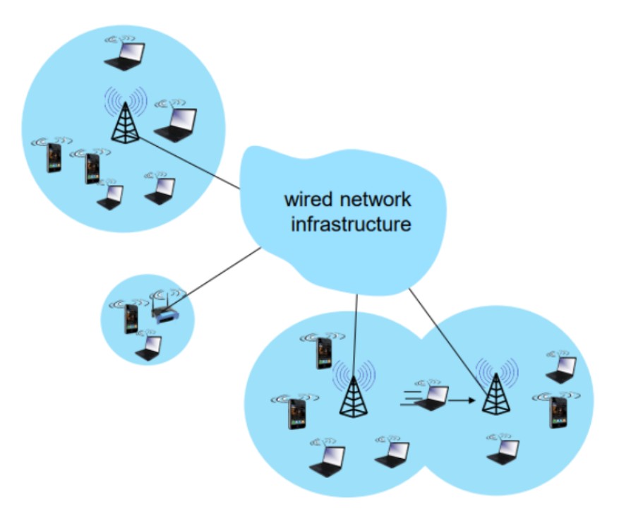
So the first thing that we had to be focus is at the ‘wireless hosts’ which is the laptop, smartphone, and other IoTs. Specifications: - Running applications - May be stationary (non-mobile) or mobile
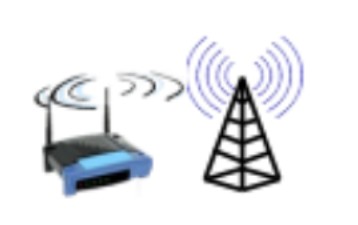
For the base stations, they typically connect to wired network. Examples: cell towers, access points. Access point (AP): It is a device that connects wireless devices to a wired network. AP acts as a bridge between wireless devices and the wired network.

Wireless Link
Wireless link is a type of network connection that allows devices to connect to each other without the use of cables. It is a means of transmitting data over a wireless network without requiring physical wires. Some examples of wireless links include Wi-Fi, Bluetooth, and cellular networks. It is usually made by radio waves, which are transmitted and received by wireless devices.
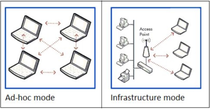
Infrastructure mode
Infrastructure mode is a type of wireless network mode where wireless devices connect to a wired network through a wireless access point. The access point acts as a bridge between the wireless devices and the wired network, allowing wireless devices to communicate with other devices on the network.
Ad hoc mode
Ad hoc wireless networks operate differently from traditional networks that rely on a central wireless base station like a Wi-Fi router. In an ad hoc network, a device within the network assumes the role of coordinating message exchange among all the nodes. Instead of relying on a dedicated infrastructure, individual wireless devices in the network transmit and receive packets directly from one another. These networks are particularly valuable in situations where wireless infrastructure is unavailable, such as when there are no access points or routers nearby, and it is not feasible to extend cabling to enable wireless communication in that area.
Ad hoc mode can be easier to set up than infrastructure mode when connecting a handful of devices without requiring a centralized access point. However, there are some disadvantages to ad hoc networks, such as poor wireless communication range issues and difficulty in managing as the number of devices increases.
Wireless network taxonomy
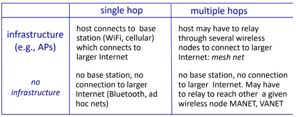
Differences between wireless links and wired links:
-
Speed: Wired links are typically faster and more reliable compared to wireless links. Wired connections have dedicated bandwidth, while wireless connections share bandwidth among multiple devices.
-
Distance: Wired links are limited by the length of the connecting cable, whereas wireless links can cover greater distances without the need for physical cables. However, wireless links can be affected by interference and obstacles like walls or buildings.
-
Security: Wired links are generally considered more secure as they are less susceptible to hacking or interference. Although wireless links can be encrypted to enhance security, they are still more vulnerable than wired links.
-
Cost: Wired links are generally more cost-effective since they do not require additional hardware like routers or access points. However, if devices are located far apart, the cost of wired links may increase due to longer cable requirements.
-
Mobility: Wireless links offer greater mobility as devices can move freely without being restricted by cables. However, the mobility of wireless links is limited by the range of the wireless network.
WiFi: 802.11 wireless LANs
The IEEE 802.11 is the first WLAN standard that has secured the market in large extent. The primary goal of the standard was the specification of a simple and robust that offers time bounded and asynchronous services
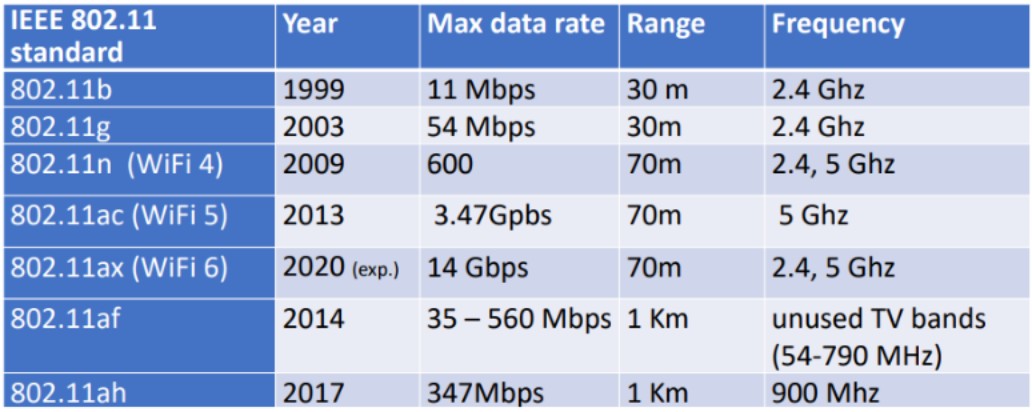
Here's an overview of the different versions of IEEE 802.11 and their features:
IEEE 802.11b: Supports data rates up to 11 Mbps in the 2.4 GHz frequency band. IEEE 802.11a: Supports data rates up to 54 Mbps in the 5 GHz frequency band. IEEE 802.11g: Supports data rates up to 54 Mbps in the 2.4 GHz frequency band. IEEE 802.11n: Supports data rates up to 600 Mbps in the 2.4 GHz and 5 GHz frequency bands. IEEE 802.11ac: Supports data rates up to 6.93 Gbps in the 5 GHz frequency band. IEEE 802.11ax: Supports data rates up to 11 Gbps in the 2.4 GHz and 5 GHz frequency bands.
802.11 Services
Basic Services Set (BSS) The basic services set contain stationary or mobile wireless stations and a central base station called access point (AP). The use of access point is optional. If the access point is not present, it is known as stand-alone network. Such a BSS cannot send data to other BSSs. This type of architecture is known as adhoc architecture. The BSS in which an access point is present is known as an infrastructure network.
Extend Service Set (ESS) An extended service set is created by joining two or more basic service sets (BSS) having access points (APs). These extended networks are created by joining the access points of basic services sets through a wired LAN known as distribution system. The distribution system can be any IEET LAN.
Collision avoidance 802.11 standard uses Network Allocation Vector (NAV) for collision avoidance.
The procedure used in NAV is explained below:
-
Whenever a station sends an RTS frame, it includes the duration of time for which the station will occupy the channel.
-
All other stations that are affected by the transmission creates a timer caned network allocation vector (NAV).
-
This NAV (created by other stations) specifies for how much time these stations must not check the channel.
-
Each station before sensing the channel, check its NAV to see if has expired or not.
-
If its NA V has expired, the station can send data, otherwise it has to wait.
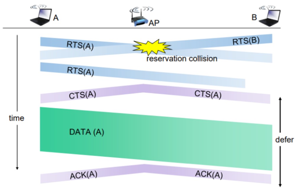
There can also be a collision during handshaking i.e. when RTS or CTS control frames are exchanged between the sender and receiver. In this case following procedure is used for collision avoidance:
-
When two or more stations send RTS to a station at same time, their control frames collide.
-
If CTS frame is not received by the sender, it assumes that there has been a collision.
-
In such a case sender, waits for back off time and retransmits RTS.
802.11 Addressing

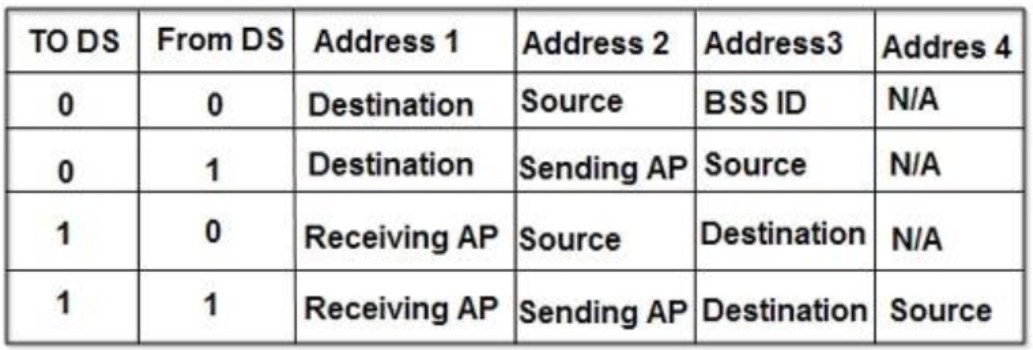
There are four different addressing cases depending upon the value of To DS And from DS subfields of FC field.
Each flag can be 0 or 1, resulting in 4 different situations.
-
If To DS = 0 and From DS = 0, it indicates that frame is not going to distribution system and is not coming from a distribution system. The frame is going from one station in a BSS to another.
-
If To DS = 0 and From DS = 1, it indicates that the frame is coming from a distribution system. The frame is coming from an AP and is going to a station. The address 3 contains original sender of the frame (in another BSS).
-
If To DS = 1 and From DS = 0, it indicates that the frame is going to a distribution system. The frame is going from a station to an AP. The address 3 field contains the final destination of the frame.
-
If To DS = 1 and From DS = 1,it indicates that frame is going from one AP to another AP in a wireless distributed system.
Mobility in the Same IP Subnet
When companies and universities deploy multiple wireless LANs (BSSs) within the same IP subnet to increase the range, the issue of mobility arises. This means that devices connected to one BSS may need to seamlessly move to another BSS without interrupting their ongoing TCP sessions. In cases where the BSSs are part of the same subnet, mobility can be managed straightforwardly. However, if the BSSs are in different subnets, more advanced mobility management protocols are required.
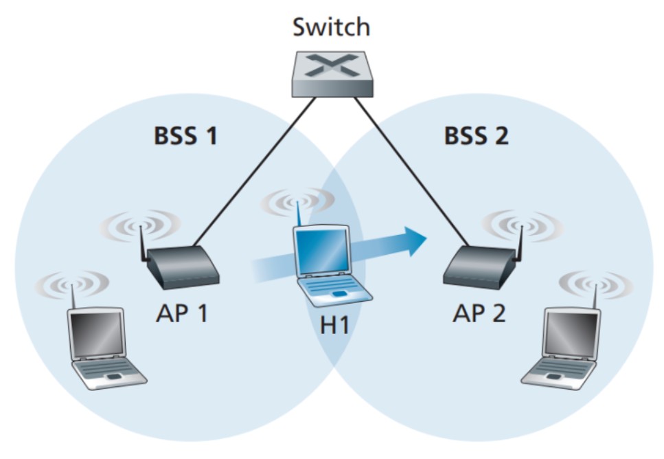
In the specific example shown in the picture above, two interconnected BSSs (BSS1 and BSS2) are depicted with a host (H1) moving from BSS1 to BSS2. In this scenario, since the interconnection device between the BSSs is not a router, all the devices within the BSSs, including the access points (APs), belong to the same IP subnet. Therefore, when H1 moves from BSS1 to BSS2, it can retain its IP address and ongoing TCP connections. If a router were used as the interconnection device, H1 would need to obtain a new IP address in the new subnet, which would disrupt and eventually terminate its TCP connections. This issue can be addressed using network-layer mobility protocols like mobile IP.
Now, let's focus on what happens specifically when H1 moves from BSS1 to BSS2. As H1 moves away from AP1, it detects a weaker signal and starts scanning for a stronger signal. H1 receives beacon frames from AP2, which may have the same SSID as AP1. H1 then disassociates from AP1 and associates with AP2, maintaining its IP address and ongoing TCP sessions.
Regarding the switch in the picture above, it needs to be aware of the host's movement from one AP to another. Switches have a self-learning feature and automatically build their forwarding tables. However, they were not designed to handle highly mobile users who want to maintain TCP connections while moving between BSSs. Before the host's movement, the switch has an entry in its forwarding table that associates H1's MAC address with the outgoing switch interface through which H1 can be reached. If H1 is initially in BSS1, incoming datagrams destined for H1 will be directed to H1 via AP1. Once H1 associates with BSS2, the frames need to be directed to AP2. One solution is for AP2 to send a broadcast Ethernet frame with H1's source address to the switch immediately after the new association. When the switch receives this frame, it updates its forwarding table to allow H1 to be reached via AP2. The 802.11f standards group is working on an inter-AP protocol to address these and related issues.
Advanced Capabilities
In concluding our coverage of 802.11 networks, it's important to mention two advanced capabilities. While not fully defined in the 802.11 standard, these capabilities are made possible by the standard's specified mechanisms. This flexibility allows vendors to implement these capabilities using their proprietary approaches, potentially giving them a competitive edge.
Rate Adaptation
Consider a mobile user who starts 20 meters away from the base station with a high SNR. They can use a modulation technique that provides high transmission rates with low bit error rate (BER), resulting in successful communication. However, as the user moves away from the base station, the SNR decreases, and if the modulation technique remains the same, the BER will become too high, leading to incorrect frame reception.
To address this, some 802.11 implementations incorporate rate adaptation, which dynamically selects the appropriate modulation technique based on the current channel conditions. If two consecutive frames are transmitted without receiving an acknowledgment (indicating bit errors), the transmission rate is reduced. Conversely, if ten consecutive frames are acknowledged or a timer expires, indicating good channel conditions, the transmission rate is increased. This rate adaptation mechanism resembles TCP's congestion control approach. When conditions are favorable (acknowledgments received), the transmission rate is increased until issues occur (lack of acknowledgments), prompting a rate reduction.
802.11 rate adaptation and TCP congestion control share a similar concept to a child persistently asking for more privileges until the parents set limits. Similarly, the transmission rate increases until an issue arises, and then it is reduced. Several other schemes have been proposed to enhance this basic rate adjustment mechanism.
Power Management
The 802.11 standard includes power-management capabilities to help mobile devices conserve power. These capabilities allow 802.11 nodes to minimize the time they need to stay active for sensing, transmitting, receiving, and other tasks.
Here's how 802.11 power management works: A node can switch between sleep and wake states, similar to a sleepy student in a classroom. When a node wants to go to sleep, it sets the power-management bit in the header of an 802.11 frame to 1. The node then sets a timer to wake up just before the access point (AP) sends its beacon frame (usually every 100 milliseconds).
Since the AP knows the node is going to sleep based on the power-management bit, it avoids sending any frames to that node and buffers them for later transmission. When the node wakes up right before the AP's beacon frame, it quickly becomes fully active (this wakeup process takes only 250 microseconds).
The AP's beacon frames contain a list of nodes that have buffered frames at the AP. If there are no buffered frames for the node, it can go back to sleep. However, if there are buffered frames, the node can explicitly request them by sending a polling message to the AP.
By utilizing a short wakeup time, checking for buffered frames, and taking advantage of the 100-millisecond inter-beacon time, a node that has no frames to send or receive can remain asleep 99% of the time. This results in significant energy savings, making power management a valuable feature for mobile devices.
4G/5G Cellular Networks
In the previous section, we discussed how a host can connect to the Internet using an 802.11 WiFi access point (AP) in its vicinity. However, APs have limited coverage areas, and it's not feasible for a host to associate with every AP it encounters. In contrast, 4G cellular network access has become widely available. Studies show that 4G signals are found more than 90% of the time in the US and even higher percentages in countries like Korea. This widespread access enables activities like streaming HD videos and participating in videoconferences while on the move.
Cellular networks are divided into smaller coverage areas called cells, and each cell has a base station that communicates with mobile devices within its range. The coverage area of a cell depends on various factors such as the transmitting power of the base station and devices, obstacles in the area, and antenna characteristics.
In this section, we provide an overview of 4G and emerging 5G cellular networks. We'll examine the wireless connection between mobile devices and base stations, as well as the carrier's all-IP core network that connects the wireless link to other carrier networks and the larger Internet. Surprisingly, we'll find many similarities between the architecture of 4G networks and the principles we've learned about in our study of the Internet, such as protocol layering, network interconnection, and centralized control. Although the implementation may differ, we'll encounter familiar concepts and Internet protocols in the cellular network context.
We'll cover more topics related to 4G, such as mobility management and security, in later sections. It's important to establish the fundamental principles before delving into these specific areas. Please note that our discussion of 4G and 5G networks in this section will be brief, as cellular networking is a vast field with numerous specialized courses and extensive literature available for further exploration.
Just like the Internet has RFCs (Request for Comments) that define its architecture and protocols, 4G and 5G networks are also defined by technical specifications. These specifications, freely available online, serve as the definitive source for understanding the standards and protocols of cellular networks. While they can be dense and detailed, they provide comprehensive answers to specific questions.
Elements of 4G LTE Architecture
Mobile Device:
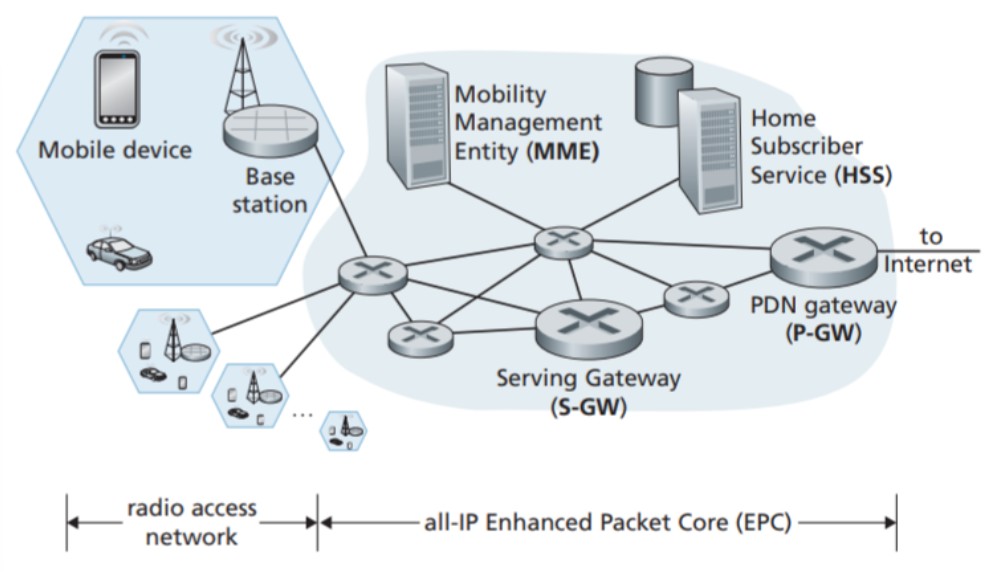
This refers to devices such as smartphones, tablets, laptops, and IoT devices that connect to a cellular network. These devices run various applications like web browsers, map apps, voice and videoconference apps, mobile payment apps, and more. Similar to hosts at the edge of the Internet, mobile devices implement the complete 5-layer Internet protocol stack, including the transport and application layers. They have an IP address obtained through NAT (Network Address Translation) and a unique 64-bit identifier called the International Mobile Subscriber Identity (IMSI) stored on the SIM card. The IMSI identifies the subscriber and their home cellular carrier network. In this textbook, we'll refer to mobile devices as mobile devices rather than using the official term "User Equipment (UE)" in 4G LTE. It's important to note that a mobile device doesn't always have to be mobile; it can also be a fixed sensor or camera.
Base Station:
The base station is located at the network edge of the cellular carrier and handles the management of wireless radio resources and mobile devices within its coverage area, represented as a hexagonal cell in the picture above. Mobile devices interact with the base station to connect to the carrier's network. The base station manages device authentication and resource allocation.
Home Subscriber Server (HSS):
The HSS is a control-plane element and acts as a database storing information about mobile devices associated with the network. It works together with the MME for device authentication.
Serving Gateway (S-GW), Packet Data Network Gateway (P-GW), and other network routers: These routers are located on the data path between the mobile device and the Internet. The P-GW provides NAT IP addresses to mobile devices and performs NAT functions. They act as gateways between the LTE network and the larger Internet.
Mobility Management Entity (MME):
The MME is a control-plane element responsible for authenticating mobile devices and setting up tunnels on the data path between the device and the PDN Internet gateway router. It also maintains information about the device's location within the cellular network.
Authentication:
Both the network and the mobile device need to authenticate each other. The MME acts as a middleman between the mobile device and the Home Subscriber Service (HSS) for authentication purposes.
Path setup:
The data path from the mobile device to the carrier's gateway router involves a wireless first hop between the device and the base station, and concatenated IP tunnels between the base station, Serving Gateway, and PDN Gateway. These tunnels are set up and controlled by the MME to facilitate device mobility.
Cell location tracking:
As the mobile device moves between cells, the base stations update the MME about its location. When the device is in sleep mode and moving between cells, the MME takes responsibility for locating the device through a process called paging.
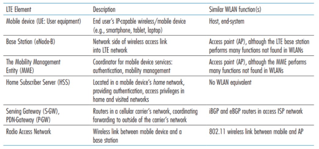
The table above provides a summary of the key LTE architectural elements and compares them with the functions encountered in the study of WiFi wireless LANs (WLANs).
LTE: Data Plane Control Plane Separation
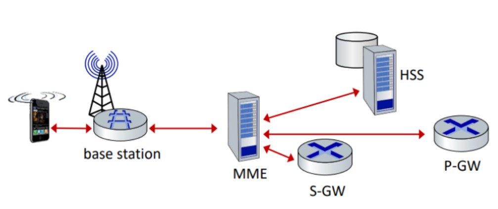
Control plane: new protocols for mobility management, security, authentication (later)
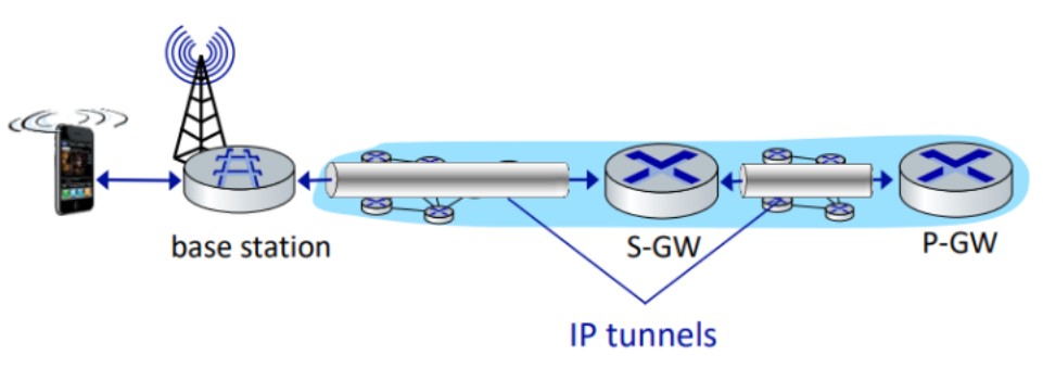
Data plane: new protocols at link, physical layers, extensive use of tunneling to facilitate mobility.
LTE Data Plane Protocol Stack: First Hop
The LTE data plane protocol stack consists of several layers, with the first hop being the Radio Access Network (RAN) and the mobile device (UE). The protocol stack can be divided into the following layers:
- Packet Data Convergence Protocol (PDCP)
- Radio Link Control (RLC)
- Medium Access Control (MAC)
- Physical (PHY)
- Radio Link
The PDCP layer processes RRC messages in the control plane and IP packets in the user plane. Its main functions include header compression, security (integrity protection and ciphering), and support for reordering and retransmission during handover.
The RLC layer is responsible for segmentation and reassembly of upper layer packets to adapt them to the size that can be transmitted over the radio interface. It also performs retransmission to recover from packet losses and reordering to compensate for out-of-order reception due to HARQ operation in the layer below.
The MAC layer manages the requesting and use of radio transmission slots. It is responsible for scheduling and coordinating the transmission of data between the UE and the eNodeB.
The PHY layer is responsible for the transmission and reception of data over the air interface. It includes modulation, coding, and channel estimation functions.
The Radio Link layer provides an end-to-end radio transmission service over a physical radio link, connecting the UE with the eNodeB.
LTE Data Plane Protocol Stack: Packet Core
The LTE data plane protocol stack for the packet core involves encapsulating data packets over GTP/UDP/IP. The two layers of IP networking are the end-to-end layer and the EPC local area network. The end-to-end layer provides connectivity between the user and the remote host, while the EPC local area network involves all eNB nodes, SGW nodes, and PGW nodes.
The GTP-U protocol operates within the User Plane of the GPRS Core Network, carrying encapsulated T-PDUs and signaling messages between GTP-U Tunnel Endpoints. GTP-U Tunnels are used over various interfaces in the Evolved Packet System (EPS). The transport bearer is identified by the GTP-U TEID and the IP address.
In summary, the LTE data plane protocol stack for the packet core encapsulates data packets over GTP/UDP/IP, with the GTP-U protocol operating within the User Plane of the GPRS Core Network to transport user data packets between different network components.
LTE Data Plane: Associating with a BS
In the LTE data plane, associating with a base station (BS) involves a mobile device finding a primary sync signal, locating a second sync signal on the same frequency, and then receiving broadcast information from the BS, such as channel bandwidth, configurations, and cellular carrier info. The mobile device may receive information from multiple base stations and cellular networks. After finding the desired BS, the mobile device still needs to authenticate, establish a state, and set up the data plane. The MAC sublayer plays a crucial role in multiplexing/demultiplexing RLC protocol data units and managing logical and transport channels.
LTE Mobiles: Sleep Modes
LTE mobile devices can put their radio to "sleep" to conserve battery life. They have two modes: light sleep and deep sleep. In light sleep, the radio wakes up periodically (100s of milliseconds) to check for downstream transmissions. In deep sleep, the radio wakes up after 5-10 seconds of inactivity. If the mobile device changes cells while in deep sleep, it needs to re-establish the association.
Global Cellular Network: A Network of IP Networks
A global cellular network is a network of IP networks that allows visited mobile devices to connect to various carrier networks and the public internet through inter-carrier IPXs. The P-GW (Packet Gateway) plays a crucial role in connecting home mobile devices to the home carrier network, where a Home Subscriber Server (HSS) is located. When roaming in a visited network, the mobile device may need to re-establish an association with the visited network. SIM cards store global identity information to facilitate this process.
On to 5G!
5G aims to achieve a 10x increase in peak bitrate, a 10x decrease in latency, and a 100x increase in traffic capacity compared to 4G. The new radio (5G NR) operates on two frequency bands (FR1: 450 MHz-6 GHz and FR2: 24 GHz-52 GHz) and uses MIMO with multiple directional antennas. However, it is not backwards-compatible with 4G. Millimeter wave frequencies allow for higher data rates but over shorter distances, requiring dense deployment of new base stations called pico-cells.